RF CONNECTORS AND FEEDTHRUS:
The centerline of any connector or feedthru must be located a minimum of 9/16″ from any outside corner and a minimum of 3/8″ up from the bottom or down from the top of the case, including covers. Connectors may not be closer than 3/4″ center-to-center. Feedthrus may not be closer than 5/16″ center-to-center. Connectors will be centered in height on the case unless otherwise specified.
CIRCUIT BOARDS:
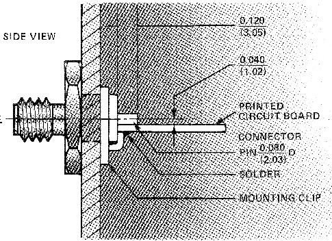
Regardless of connector type, when a PC board is installed in the case, the face of the PC board next to the connector center pin will be 0.040” off center from the connector centerline. PC boards from 0.020” to 0.070” thick can be mounted using the clips supplied. Corners of the circuit boards must be notched ¼” x ¼” to clear ruvnuts. In addition 0.100” must be removed from the side(s) of the circuit board which will have RF connectors. Circuit board thickness must be between 0.020” and 0.040” in a 3/4” high overall case. In cases 1” or more overall height circuit board thicknesses of 0.020” to 0.070” can be accommodated.
MOUNTING:
Mounting is provided by two or more 4-40 tapped holes in the base. Mounting center are ½” less than the outside dimensions of the case. Flange type bottom cover with clearance mounting holes may be obtained on special order. These extended covers and 1” longer than case size.
COVERS:
Top and bottom covers are made of 1/6” aluminum. Height of the standard Modpak cases includes covers. In specifying custom cases, be sure in include thickness of both covers (1/8” total) in overall height to obtain overall case height from ¾” to 3”.
FINISH:
Standard models are nickel-plated per MIL-QQ-N-290. A variety of other finishes are also available.
NOTES:
- All Modpak cases are 6063-T52 alloy; 1/8” will thickness. All Modpak covers are 5052-h32 alloy x 1/6” thick
- Each custom configuration specified includes: connectors, feedthrus as required, double “D” hole punching as specified, hex nuts, mounting clips, top, bottom covers (with rivnuts installed in bottom cover).
